Boatmonitor X1 Manual
Congratulations — you have upgraded your boat with a watchman who looks after it 24/7.
This manual is divided into several sections in the menu above. Read it carefully and make sure to scroll down to view all information.
This section provides an Overview.
Device: explains the connectors, mounting instructions, and buttons.
Cable: contains important instructions on how to connect the device to the batteries.
After completing the installation, you can refer to the App section to learn how to log in and use the software. Finally, we explain several details and considerations regarding the Settings menu.
Parts List
- Boat monitor
- Battery connection cable
- Antenna for GPS and 4G
- 1 Battery connection cable for two batteries
- 2 Fuses (pre installed in the battery cable 5A max)
- 4 Mounting screws
- 2 Mounting plates
- 4 Mounting-plate screws
- 2 Heavy-duty zip ties
System
The boat monitor provides a compact solution for tracking and recording onboard data, built to:
- Monitor and log voltages of 2 batteries
- Log bilge pump activity
- Log GPS location
- Detect impact on the vessel
- View and export data through an app
The system consists of:
- A main unit with three control buttons
- Four connection interfaces
- A mobile Boat monitor App for configuration and data readout
2.0 Hardware

Port 1 – Battery Circuits 1 and / or 2
Connects to max two onboard batteries (12/24V). Measures voltage.
Port 2 – Pump & Bilge Switch
Provides power to the pump and reads the bilge switch. Supports pump loads up to 4A continuous.
Port 3 – 4G antenna Connection
Port 4 – GPS antenna Connection
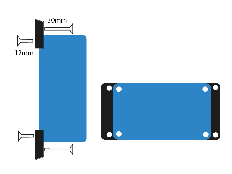
2.1 Mounting
Mount the GPS antenna (3 m cable) — either outside through the deck or under the cockpit seats; when choosing the location, take the 2.5 m battery cable into account. Select a dry spot.
The boat monitor can be secured with screws with the supplied mounting feet; you can also fasten the feet with a zip tie instead of using 30 mm screws.
Torx screws (T20)
- 30 mm screws for mounting to the boat
- 12 mm screws for attaching the base plate to the housing
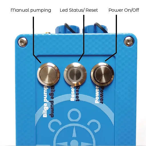
2.2 Operation with Three Buttons
Button
Function
Action
1 Power On/Off
On/Off
Push 1 time
2 Reset
Status LED/ Reset
Push and release
3 Manual Pumping
Pump On
Press and hold
LED Status
- Green: System active
- Blue: Transmitting data
- Orange: Starting up or shutting down
- Purple: Impact detected
- Red: Error or warning
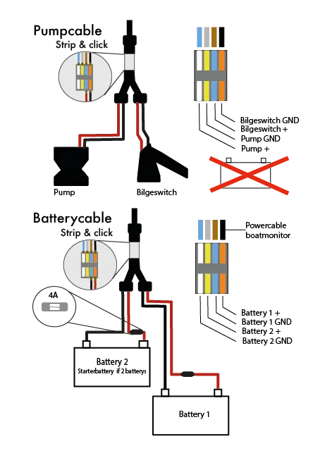
3.1 Cabling overview

3.2 Battery Configuration
The Boatmonitor can measure two battery circuits. Battery one (1) supplies power to the Boatlogger.
In a situation with two batteries, we recommend connecting the starter battery as battery two(2), so that it remains unloaded and is only monitored.
3.3 Connecting cables
The supplied battery cable and the pump cable (purchased separately) look similar but have different connectors. The battery cable must always be connected to the “open connector (see image under tab ‘Device’; Port 1)” on the unit. The pump/bilge connects to the shielded connector (tab ‘Device” on Port 2).
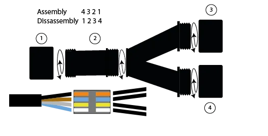
3.4 The Y-splitter
The handy Y-splitter has four wires in the central block. To prevent excessive twisting, follow the assembly sequence shown below. Do not rotate the ‘V’ section.
How to use our Web-application
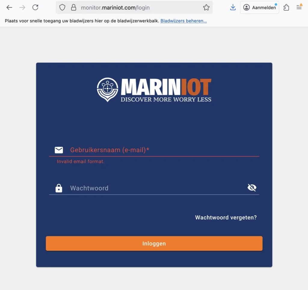
Login
You can find the login option in the top menu on our website, www.mariniot.com. You can also go directly to https://monitor.mariniot.com/login
.
Enter your username (email) and password here.
Password recovery
Click on the field password forgotten, open your e-mail box and click the link to reset your password.
Main menu
The design philosophy of Mariniot is to make the product simple, easy, and functional—from installation to everyday use. This philosophy is reflected in the main menu of our web app. Each element will be explained in the following sections.
Alarms
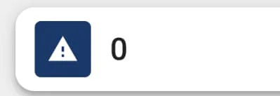
Below our logo, you will see a warning triangle with a number. If the triangle is orange and the number is not zero, you can view the alarms by clicking on this bar. A menu will open showing the active alarms along with a brief description. For example:
- – Bilge alarm or pump activity
- – Geofence break out
- – Battery over- or undervoltage
- – Impact detection above a set threshold (in Settings)
Map
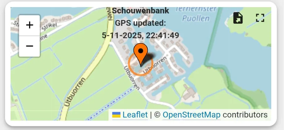
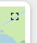
In the main menu a small map shows your position. By clicking on the small square in the right top corner you get a full screen view. This square is seen in maps and graphs throughout the app. By clicking on it you can toggle between full screen or split screen.
Geofence

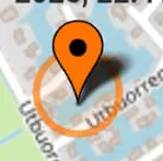
When the geofence is activated, you will see a small circle around your boat. This circle is set to approximately 50 meters by default, but you can adjust it in the settings.
If you make the circle too narrow, GPS inaccuracy may trigger alarms too quickly. When your boat moves outside this circle, you will receive an alarm by SMS as well as a notification in the main menu of the Mariniot app. When you go sailing, it is advisable to switch the geofence off. Once you return to the harbor, you can turn it on again. It functions as an anchor alarm or theft alarm.
Travel Log

In the travel log, you can select a time frame in the small grey text under the label Trip Map. By clicking on it, you can choose both a timeframe and a date range. The travellog displays a sequence of data points within the selected period. Depending on the mode you were using, it may be useful to increase the number of data points using the button at the bottom of the Date Range / History panel. This will plot additional points on the map. At the bottom of the triplogscreen left, you can replay your trip at different speeds. In the event of a collision, you can find the position of your boat using the timestamp of the collision shown in the Impact screen.
Batteries

In the Battery menu, you can view the voltage of your connected battery circuits. In this example, the starter battery is shown in red and the house battery in green. The graph is set to a seven-day view by default, but you can change this under Battery Voltage. When you initially open the menu, the graph may appear small—use the small rectangle in the upper-right corner to switch to full view.
In this case, the boat charges for one hour every morning. The small peaks in the curve come from a solar panel under a cover that still receives some light. Minor fluctuations in the starter battery are likely caused by temperature changes affecting the voltage. You can set minimum and maximum voltage limits in the settings menu.
Impact

The impact sensor measures impact on your boat. Give it some time to play with the settings to get a correct reading. If it is set to sensitive you get to many measurements. To wide the device will not register anything. Also keep in mind that a heavier boat needs a more sensitive reading. While a lighter boat will give more response. Also the area and condition you are sailing in should be considered. Give it some time to read out relevant data. The peaks are an indication . Combined with a trip log and timestamp you can sometimes retrieve why your ship has damage and where it happened. This is especially interesting in the rental market.

Under the label Impact Sensor, there is grey text that opens a menu. By default, the impact sensor is set to a one-day view.

Our boat monitor uses a unique algorithm that analyzes not only the impact in G-force, but also estimates the absorbed energy. To make this work accurately on your boat, you need to provide a few parameters, such as the boat’s material, length, and weight, as well as the sailing conditions.
The table below gives an indication of the values you should set for your vessel:
Bilge level

During normal operation this is the most boring screen of your app. But nevertheless when your boat is getting water. We have you covered. First there is an option to connect the monitor without a switch. In that case the buttons; Autopump/Silence Alarm/Pump are not functioning. But you will see the switch activity and also recieve an sms Alarm. You can buy pumps in our webshop.

By now, you probably know that you can adjust the timeframe or history by clicking the grey text on the left. There is also a download button, and you can click the dotted square in the upper-right corner to switch to full-screen view.
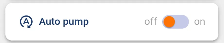
When switched on, the water in your bilge will automatically be pumped out when the bilge switched is triggered, through a filter, or into a reservoir. Only use this function when you are certain that the water is free of oil or other contaminants, and that your setup does not pump out the last 3 to 4 centimeters of bilge water. When there is an engine around.
Do not use autopump if the water is potentially contaminated.

When Auto Pump is turned off and the bilge switch detects water in your boat, an acoustic alarm will sound from your pump. After being notified about water in the bilge, you can remotely turn off the alarm. You will receive an SMS, an alert in the app, and—onboard or in the harbor—an audible alarm that can be heard by nearby boats or persons nearby.
This alarm can be switched off, by silencing it.

You can force to pump to start running and it will run for 5 minutes. After 5 minutes it is automatically switched off. It will also automatically switch of In case dry run (no water) or over current conditions are detected (pump stuck). The threshold values for dry run and overcurrent can be set in settings menu.
The settingsmenu

The settings menu hosts a few important functions in the operation of your boatmonitor.
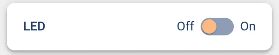
In the effort to make your BoatMonitor as energy-efficient as possible, you can turn the status LED on or off. In practice, the status LED is only useful when you are on board or performing maintenance, as it shows what the device is currently doing.
LED Status Indicators
- Green: System active
- Blue: Transmitting data
- Orange: Starting up or shutting down
- Purple: Impact detected
- Red: Error or warning

In High Performance mode, the BoatMonitor performs a routine check every 10 seconds and consumes approximately 0.8 watts. When you switch this mode off, the device enters Guarding/Sleep mode, waking up every 10 minutes to run a check. Energy usage drops dramatically in this mode, and if an event occurs—such as a bilge alarm or impact—the device will automatically wake up and switch back to High Performance mode.
In practice, we recommend using High Performance mode only while sailing, as it provides much more detailed GPS tracking. In most other situations, especially when the boat is in the harbor, you can safely turn this function off.

With pairing the device can make a connection with supported wireless sensors in your ship. For example a temperature sensor or smart wall plugs. You can find these in our web shop.

If your BoatMonitor is not responding, you can press Reset. The device will restart and check whether any software components are missing. If this does not resolve the issue, there is also a physical reset button on the device. If that still doesn’t work, power the device off for 10 seconds and then turn it back on.
If the problem persists, please contact our support team. We are committed to providing a reliable experience and will do our best to resolve any issues with your product.

In this menu, you can adjust various settings that influence how the BoatMonitor operates.
This section contains adjustable values that you can tailor to your boat’s situation—for example, the alarm thresholds for under- and over-current, or the geofence radius, which is set to 50 meters by default.
Please note that if the settings are too narrow, the monitor may generate excessive alarms, switch too often into High Performance mode, and consume more battery power and data. In most cases, you can leave these settings as they are.
The only exception is the impact sensitivity. You may need to fine-tune this value: around 0.1 for heavy boats (very sensitive) and up to 2.0 for light or flexible boats (less sensitive).